Installation Process
Contents – (Part 1)
Credibility & Duty of Care
Competency
Doorsets are not freestanding products and they will not provide any design performance unless competently designed and installed into a suitable structural opening.
Design & Specification
Products designed and specified for the right application and will perform correctly in the event of a fire.
Manufacture
Hanson & Beards Ltd products are manufactured under Trada ‘Q’ Mark, an approved third-party certification scheme to the requirements of BS 476 part 22, or EN 1634 part 1.
Installation
Installed by third party certified installers in line with Hanson & Beards Ltd installation instructions.

Credibility & Duty of Care
Why Fire Door Installation Matters…
Any errors made in the installation process can have dangerous consequences…
1. The door will not perform in the event of a fire, causing fire and smoke to spread through a building.
2. The building is not correctly protected and property insurances may be invalidated.
3. If you are legally responsible for ensuring the fire doors are installed correctly you are liable and can be prosecuted.
4. Hanson & Beards product certification and warranties are invalidated.

Important Information Before You Start
Hanson & Beards recommend that the doorset Installer is certified by a recognised third-party UKAS assured installation scheme, such as Trada or Firas.

Important Information Before You Start
Joinery products should always be installed after Wet Trades have finished and the building moisture levels have returned to normal.
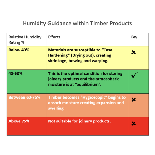
Joinery installed in areas where moisture levels are high are susceptible to hygrothermal (Moisture & Heat) effects. These conditions can result in product distortion and warping or excessive shrinkage.
The building/area relative humidity should fall between 40-60% RH for internal joinery products.
Preparation for Installation
It is the responsibility of the specifier to ensure that the structural opening is capable of supporting the weight of the doors.
It is the responsibility of the installer to ensure that the structural opening is square and plumb and has sufficient tolerance to fit the frame.
Door product weights can be provided by Hanson and Beards upon request.
Preparation for Installation
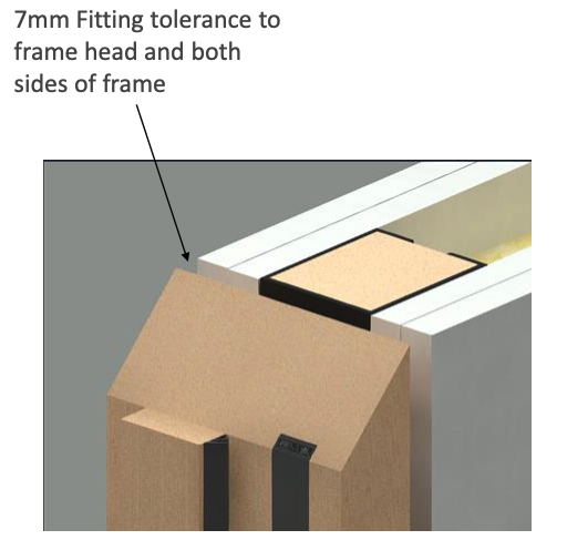
Hanson & Beards doorsets are manufactured to achieve a 7mm clearance against the structural opening dimension. 14mm undersize in width (7mm each side) and 7mm in height.
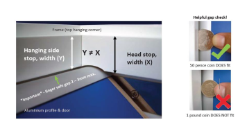
Gaps below 5mm may inhibit the ability to apply fire stopping products!
Preparation for Installation
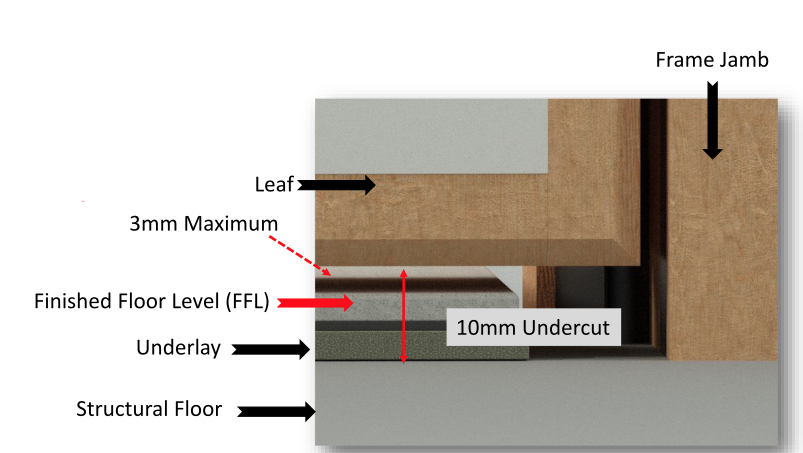
Unless specified otherwise, Hanson and Beards doorsets are manufactured with a 8mm undercut as tested for fire performance.
To comply with BS 9999:2017 for smoke sealing, the gap between the Finished Floor Level and the bottom of the door cannot be greater than 3mm or must have a drop-down threshold seal.
NB: These seals can be damaged by using wedges to keep doors open, cables pulled beneath the leaf and floor protection with sharp exposed edges.
Handling, Storage & Protection
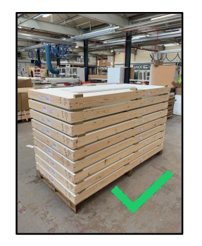
Products should not be stacked directly onto the floor. Doorsets should be stacked up to a maximum height of 1200mm with a minimum of 3x door width bearers set equally along the product length to prevent distortion/deformation.
Handling, Storage & Protection
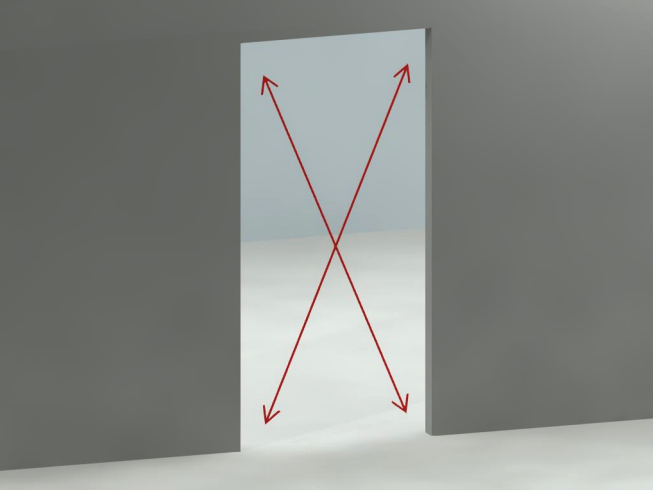
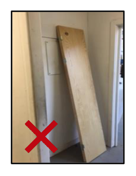
Products should not be stood upright on their ends, this causes distortion making the doorsets inoperable.
Handling, Storage & Protection
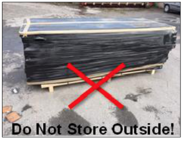
Hanson and Beards doorset products are supplied in a black shrink wrap but should never be stored outside or in areas with high levels of moisture or humidity.
Products should ideally be stored for 2 to 3 weeks close to the installation area or in a location with the same ambient conditions to allow the product to stabilise before fitting.
H&B Products can be heavy / difficult to lift and manoeuvre, you must take care to avoid injury to personnel. A manual handling assessment will be required when handling our products on your site.
Always work in strict accordance with your site manual handling policy.
Handling, Storage & Protection
At the earliest opportunity and prior to installation, check for any unforeseen issues with regard to product quality.
All primed grade products should be fully sealed within 1x week after the product has been installed with subsequent coats applied within a short time thereafter.
It is the responsibility of the installer to ensure adequate protection is given to Hanson & Beards products directly after installation and up until the point of project completion or site handover.
Adhesive tapes should not be applied to facings of a door; it can leave excessive residue or even damage the finished surfaces.

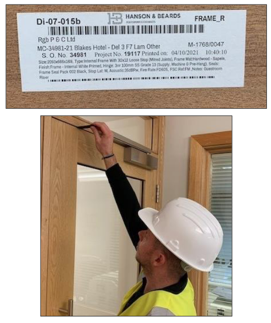
Labelling
Before fitting any product, it is the responsibility of the installer to ensure the correct product is being fitted into the correct aperture/opening.
Each product contains its own unique identifier which is specified on the product label situated on the outer frame and on the top of each door leaf.
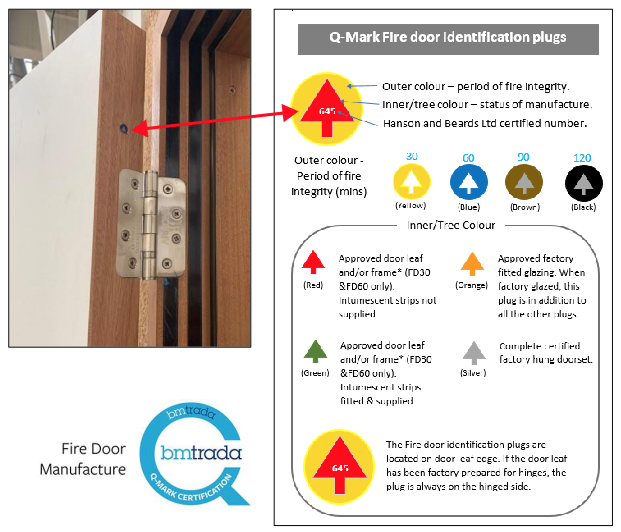
Q-Mark Approved
Hanson and Beards doorsets are tested to BS 476 part 22 and we are Q-Mark approved fire door manufacturers.

Q-Mark, Fire Plugs and Levels of Certification
Fire Plug located on the door leaf hinged side. These and the acoustic seals on the frame rebate should never be painted over.
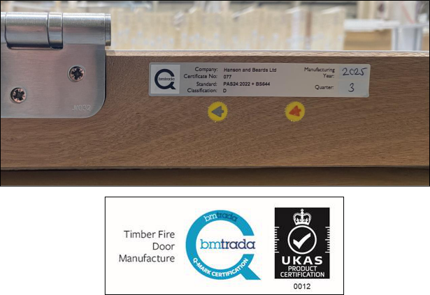
PAS 24 Identification
PAS 24 door sets will be fitted with a PAS 24: 2022 label to confirm the product meets the UK’s enhanced security performance standard.
Fire Plugs located on the door leaf hinged side. These and the acoustic seals on the frame rebate should never be painted over.
Q-Mark, Fire Plugs and Levels of Certification
Products identified with this level of certification (RED or GREEN) may not be fully prepared and therefore require further processing on site before the leaf is ready to be hung for the frame.
Further processing must be carried out directly in line with Hanson and Beards scope of certification.
Products identified with this level of certification (SILVER) require no further preparation or processing however it is permissible to fit hardware during the final installation process.
The final assembly and installation of the door set should be completed with simple tools only, such as a screwdriver.
Q-Mark Fire Door Installer Certification
To demonstrate the door sets have been installed under the supervision of a Q-Mark Approved Installer the door set must be included within the Record of Installation Activities and a GOLD label affixed to the door set (Typical Trada detail).
GOLD plugs along with the gold label can only be fitted to a SILVER certified factory hung door set.

Contents – (Part 2)
Installation
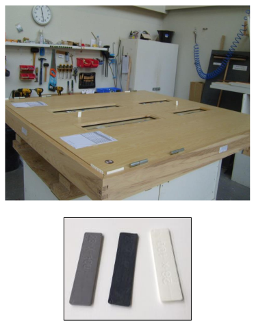
Hanson and Beards Quality Control for Door Leaf / Door Frame Gaps
All doorsets are fitted together in H&B’s factory and tested for functionality before dispatch.
The factory ensures that the gap between the door perimeter and inside frame edge on single doorsets is correct by using “GO” and “NO GO” thickness gauges, these are left in the product for transportation purposes and validation of the check.
To comply with fire certification the operating gaps between the door and frame must be between 2mm and 4mm.
Double doorsets are bench tested for door leaf / frame gaps at Hanson & Beards and then disassembled for transportation purposes.
Installation
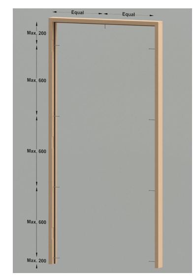
On the frame jambs, the top fixing should be no more than 200mm from the underside of the frame head. The bottom fixing should be no more than 200mm from the base of the jamb. Intermediate fixings (3no) should be located at centres no greater than 600mm.
A fixing point central in the head is mandatory for door leaves over 900mm in width.
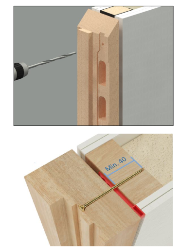
All fixing points must be pilot-drilled and counter bored to prevent the timber from splitting and cannot be distorted when fixed with screws. These are to be filled and made good afterwards.
Intumescent strips, acoustic and smoke seals are all fitted in the factory. The intumescent strip has a protective surface film to allow the frame to be painted on site.
NB: Double swing door sets to have 2 rows of fixings and rebated frames as centres above.
Installation
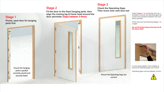
Position the frame centrally in the width of the structural opening. Pack between door frame and prepared opening immediately behind each fixing point. Ensure fixing points are securely packed and the frame cannot be distorted when fixed with screws.
Depending on the fire test evidence of the fire foam or intumescent mastic, fit the appropriate packers into the tolerance gap between frame and structural opening.
Plastic packers are allowed on FD30 fire rated door sets. On installations for FD60 or above, you must check what packer material is allowed in conjunction with the fire-stopping product test evidence.
Steel wood screw fixings should penetrate the wall by a minimum depth of 50mm to provide sufficient anchorage.
Installation
FD90 and FD120 Door Sets
The frame jambs are to be fixed to the supporting construction using 5mm x 100mm long steel screws, spaced at a maximum 600mm centres and 150mm from the top and bottom. The fixings must be of the appropriate type for the supporting construction and must penetrate to a minimum depth of 50mm.
A fixing point central in the head is mandatory for door leaves over 900mm in width.
Packers can be timber of equal density to the frame. Plywood or plastic packers may be used if fire tested for this application to BS 476: Part 22: 1987 or BE EN 1634-1.
Installation
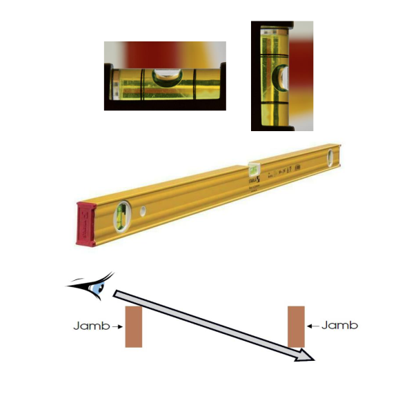
When checking the frame jambs for plumb, we strongly recommend you use either a laser or a good quality, 1800mm minimum length Spirit Level.
Only when the bubble is absolutely centered between the markings is the jamb component truly plumb.
Drill and fix the closing jamb making sure it is plumb and free from bow and twist. Sight through both legs edges to ensure they are plumb and parallel with each other.
Installation
Door frame stop laths are supplied as a loose fit item. The option is therefore provided to conceal fix the frame behind the lath if required.
Door stop laths should be mechanically fixed with 25mm length pins at the top and bottom of the lath and maximum 600mm centres.
Once the door is fitted, the door stop lath should be tight to the push face of the door. This will ensure there are no gaps and the smoke and acoustic seals perform correctly.

Installation
Installation
Installation: Operating Gaps
Use flat spacer gauges to ensure the operating gaps are between 2mm – 4mm.
Leaves must not be proud of each other or from the door frame by more than 1mm.
It is the responsibility of the installer to ensure the operating gaps are correct!
Installation
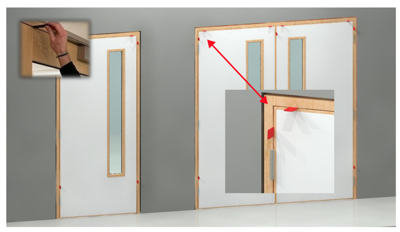
Cutting apertures in doors cannot be performed on site.
Hanson and Beards doorsets do not require dimensional alteration.
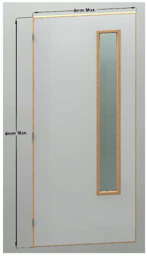
NFR, FR30 & FR60 Door leafs sold separately can be adjusted on site by 4mm maximum in either direction for fitting and easing into existing frame openings.
FR90 & FR120 are only ever produced as doorsets and cannot be altered dimensionally.
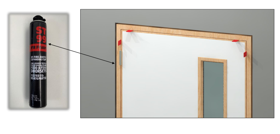
Installation – Sealing to the Structural Opening
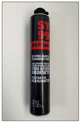
Hanson and Beards Ltd also supply fire stopping products that have been tested in their doorsets.
Installation – Sealing to the Structural Opening
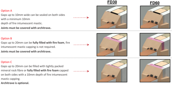
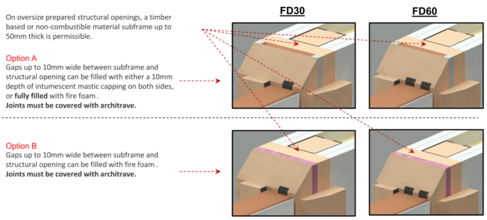
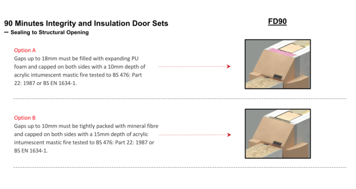
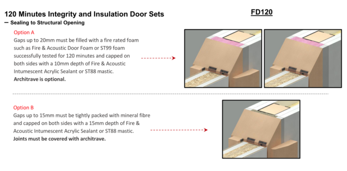
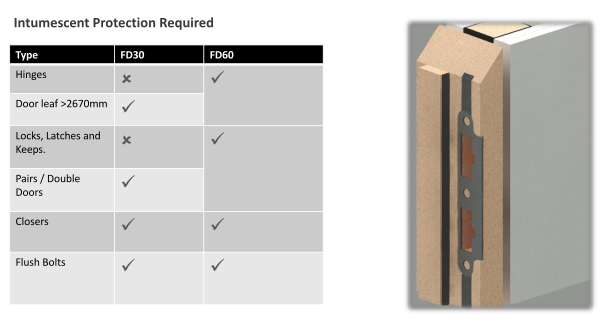
Installation: Fire Stopping Products
When selecting proprietary and certified intumescent mastics and fire foams, they must be tested to one of the following standards against the required period of fire resistance or greater:
- BS 476 part 20
- BS 476 part 22
- BS EN 1366-4
- BS EN 1634-1
Fire test evidence to comply with BS EN 1366-4 for the mastic can be between any materials and the length of the tested seal must be at least 1m, but this does not restrict its use in a fire door of greater dimensions.
Installation – Sealing to the Structural Opening
Installation – Sealing to the Structural Opening
Installation – Sealing to the Structural Opening
Installation – Sealing to the Structural Opening
Synthesis Ironmongery
Hanson and Beards manufacture doorsets with factory installed ironmongery from the Synthesis Hardware Range.
On Department for Education projects, the Synthesis Hardware Range provides CE marked, tested, certified and approved ironmongery for any project.

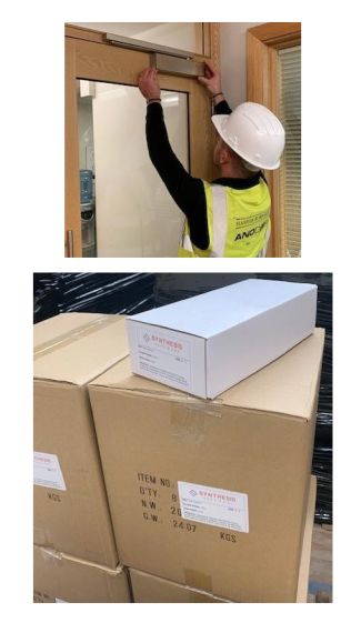
Ironmongery – Surface Mounted
Surface mounted hardware is supplied boxed with your delivery, with each door reference number noted on the boxes.
Care should be taken to ensure that when installing ironmongery with the use of battery-operated tools, the correct torque settings are applied to the tools to minimise the risk of overtightening or spinning of screw fixings.
NB: If remedial work is required to hinge screws, they should be individually removed, the screw holes correctly plugged and then re- screwed using the original factory fitted screws.
Unpack all contents carefully, ensuring no loose items are lost/discarded, including any intumescent protection. These must be installed to maintain the fire certification.
Ironmongery – Surface Mounted
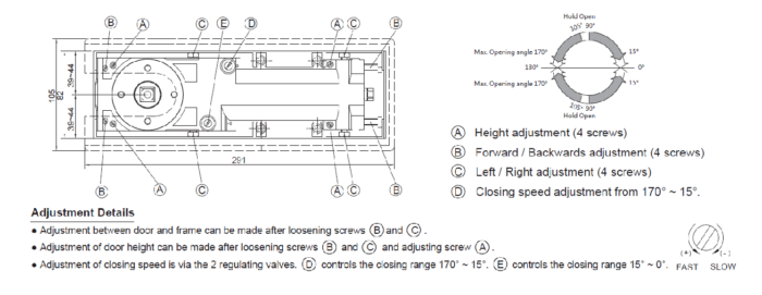
Door Closers
Essential to the overall performance and compliance of the door set and must be fitted exactly to these instructions.
Factory set to Power Size 3 for a door width of up to 950mm.
Maximum opening angle is 180°.
Should be checked after installation to ensure the closing and latching speeds are still correct and all screws are tightly fitted prior to handover.

Ironmongery – Surface Mounted
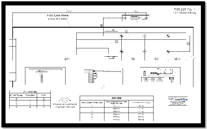
Door Closer Template
This template is provided with every surface mounted closer.
Door leaf fixings
Horizontally, the screw hole positions are 234mm & 334mm from the door edge (hinge side).
Vertically they are 22mm & 69mm down from the top of the door.
Frame fixings
The closer arm link shoe screw holes are positioned at 242mm & 287mm horizontally from the door edge (hinge side). Vertically they are set 20mm up from the frame rebate edge and must be screwed directly to the frame face and not through the architrave.
Ironmongery – Surface Mounted
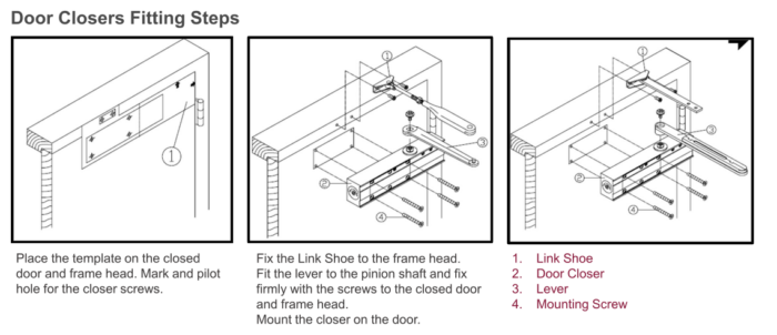
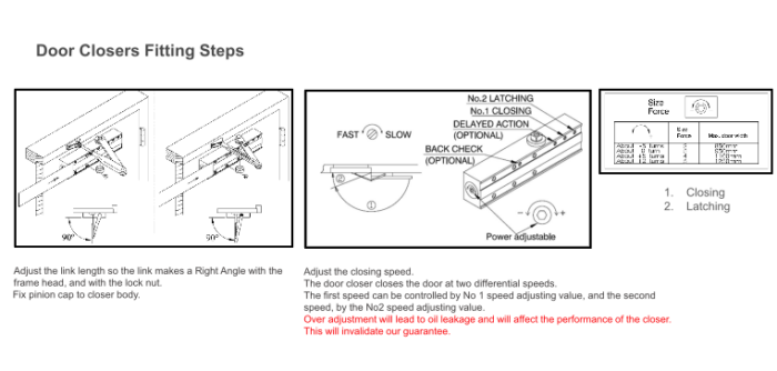
Door Closers Fitting Steps
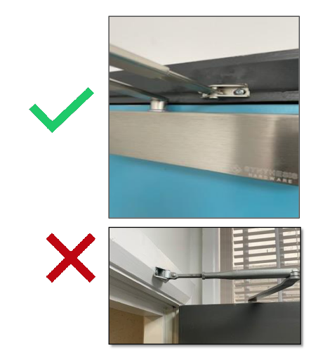
Surface mounted door closers are fire tested with the link arm shoe fixed directly into the frame head.
You should not fix the link arm shoe through the architrave.
The profile of the architrave can cause the link arm to operate at an angle and not perpendicular to the frame, therefore affecting the performance of the closer.
Prior to painting, the architraves should be fitted with a notching around the link arm shoe which is fixed directly into the frame head.
Ironmongery – Surface Mounted
Ironmongery – Surface Mounted
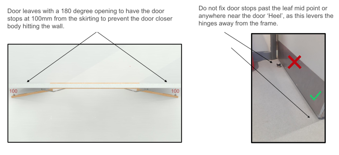
Ironmongery – Floor Fixed Door Stops
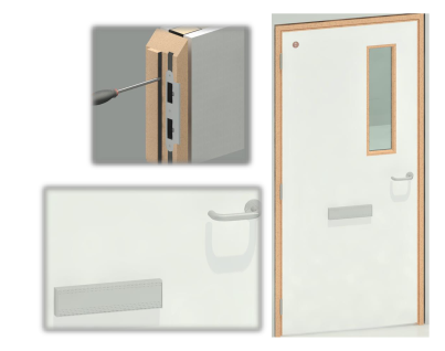
Site Prepared Ironmongery
Alternative ironmongery not supplied by Hanson and Beards Ltd can be incorporated into our fire rated doors. You must ensure that the hardware is CE marked, installed in the correct position and the appropriate intumescent is fitted around the product as required and tested.
Applies to GREEN or RED fire plugged certified products.
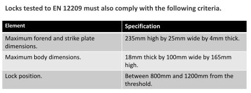
Site Prepared Ironmongery
- Locks and latches shall be tested to EN 12209.
- Electro mechanically operated locks shall be tested to EN 14846.
- Controlled door closing devices shall be tested to EN 1154.
- Electrically powered hold open devices shall be tested to EN 1155.
- Door co-ordinators shall be tested to EN 1158.
- Emergency exit hardware shall be tested to EN 179.
- Panic hardware shall be tested to EN 1125.
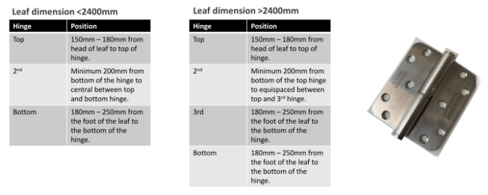
Site Prepared Ironmongery
Fire doors must be hung on a minimum of 3x hinges. Hinges must be positioned as below and fire rated leaf’s greater than 2400mm high or 1000mm wide, must have 4 hinges fitted.
Site Prepared Ironmongery
Operation & Maintenance
What the law says
Article 17 of the Regulatory Reform (Fire Safety) Order 2005 (RRO/FSO) makes it a legal requirement to ensure that fire resisting doors and escape doors are correctly installed and adequately maintained in order for them to be fit for purpose.
The Regulatory Reform (Fire Safety) Order 2005, often referred to as the RRO or FSO, applies to all buildings other than domestic housing.
The law shifts responsibility from the fire authorities for fire safety to whoever has day-to-day control of premises.
Periodic checks should be done at least every 6 months and newly occupied buildings should be checked quarterly during the first 12 months.
Doors on high traffic routes are more susceptible to damage and may require checking monthly dependent on usage.
The authorities have the power to enforce the RRO/FSO and do prosecute or even close buildings down where breaches are discovered.
Operation & Maintenance
Q-Mark Fire Door Maintenance Scheme
- Ensure the product`s service life is maximised through correct maintenance.
- Ensure the product`s fire resistance capabilities and independent third-party certification are maintained.
- Provide peace of mind that the maintainer is suitably qualified, and the certification chain is never broken.
- Only Q-Mark approved and acceptable repair techniques are employed.

Contents – (Part 3)
Special Instructions
ANOFORM – Post Formed Door Sets
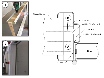
All ANOFORM door sets are fitted together in our factory and tested for functionality and correct working gap tolerances before dispatch to the customer.
1. Unscrew the loose stop lath from the back of the frame and separate the frame into two halves (sections ‘A’ & ‘B’).
2. Offer section ‘A’ into the structural opening and install the frame assembly in line with the Installation guidelines specified on pages 25 to 31. Plastic pellets can be supplied to cap the screw fixings.
Special Instructions
ANOFORM – Post Formed Door Sets (continued)
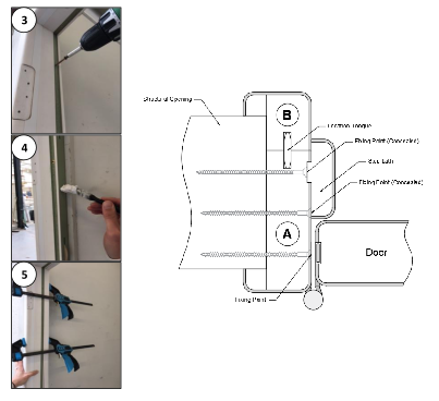
3. There is an option to conceal fix the frame through the loose stop lath housing groove. However, you must satisfy yourself that the fixing points are robust enough and do not require any additional fixing points.
4. Apply PVA glue to the back edge of section ‘A’. Line the frame parts up using the location tongue and fit section ‘B’ to ‘A’.
5. Clamp section ‘B’ to section ‘A’ and allow for the appropriate curing time for the glue.
Special Instructions
ANOFORM – Post Formed Door Sets (continued)
6. Glue and fit the stop lath into it’s housing groove. Ensure the stop lath is the correct way around. It is designed to accommodate two leaf thicknesses dependent on its orientation (47mm and 57mm).
7. Apply a colour matching proprietary branded quality silicone to all the frame joints paying particular attention to the mitres and stop laths.
Special Instructions
ANOSAFE – Integral Finger Guard Door Sets.
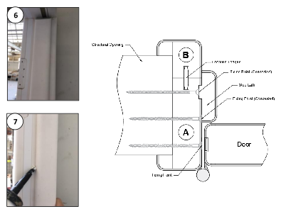
1. To release the door from the frame, rotate the door to 90° and whilst the door is being held open and steady, loosen and retract the top pivot pin and then carefully remove the door from the bottom pivot bracket.
IMPORTANT: Do not operate the adjustment screws with power tools.
2. Install the frame assembly in line with the Installation guidelines specified on pages 25 to 31.
Special Instructions
ANOSAFE – Integral Finger Guard Door Sets (continued).
3. Take particular care to ensure the hanging jamb is set straight as this will influence the finger-safe gap between the door and the frame.
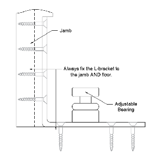
4. Use the supplied screws and plugs to fix the bottom pivot in position. Always fix the L- bracket to both floor and frame.
IMPORTANT: Care should be taken to position the L-bracket correctly as this will influence the finger-safe gap between the door and the frame.
Special Instructions
ANOSAFE – Integral Finger Guard Door Sets (continued).
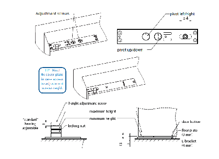
5. Determine the desired gap at the threshold and then set the height of the bottom pivot bearing accordingly.
6. To re-fit the door, position the door in a 90° open position and carefully locate the bottom strap cup onto the pivot bearing. When this has been located, raise the door to align the retracted top centre pivot pin with the top strap bearing. Extend the pivot pin to locate it in the bearing.
Special Instructions
ANOSAFE – Integral Finger Guard Door Sets (continued.
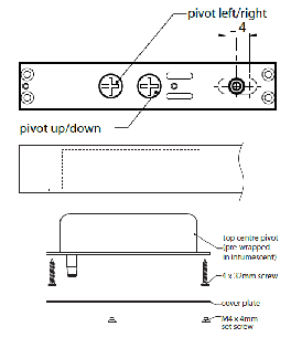
7. IMPORTANT: Ensure the pin is fully extended and securely located in the top strap bearing (this requires approximately eight full turns of the ‘retract’ / ’extend’ adjustment screw). Additionally, on the top centre adjustment ruler, look for the markers – these should be visible when the pin is fully down. If required, a half turn in the ‘retract’ direction (after fully extending) can ease the ‘hanging edge gap’ adjustment screw.
8. Check the gap at the threshold hanging side is as required. If height adjustment is necessary, remove the door, adjust the floor plate and then re-hang the door in accordance with step 4 and 5.
Special Instructions
ANOSAFE – Integral Finger Guard Door Sets (continued).
9. The finger safe gap (hanging edge) should be 2-3mm. Adjust the ‘pivot left/right’ adjustment screw on top centre until this dimension is achieved at the top of the door.
10. Check the door is swinging correctly. Check that the gap sizes around the perimeter are correct and that there is no excessive rubbing on the hanging side. Make necessary adjustments. Fix the cover plate in position over the top centre pivot when complete.
Special Instructions
Double Action Door Sets – Pivot Set.
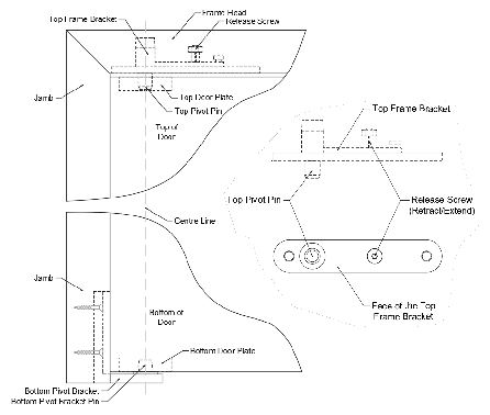
• To fit the door into the frame, rotate the door to 90° and whilst the door is being held open and steady, lower the door onto the ‘Bottom Pivot Bracket Pin’ (see illustration to the right), ensuring correct location in the bearing.
• Push the ‘Release Screw’ up to retract the ‘Top Pivot Pin’ in the ‘Top Frame Bracket’ and position the door so that the ‘Top Pivot Pin’ locates into the ‘Top Door Plate’ bush.
• Lower the ‘Top Pivot Pin’ into position in the ‘Top Door Plate’ by turning the ‘Release Screw’ clockwise.
IMPORTANT: Check and ensure the ‘Release Screw’ is fully tightened.
Special Instructions
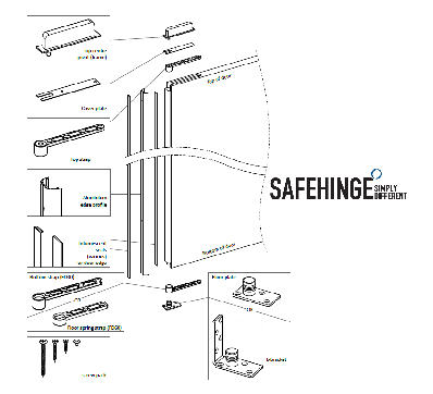
Double Action Door Sets – Floor Spring – Double Action Strap Set.
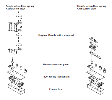
Synergy floor springs are supplied in component form, depending on whether the door is double swing or single swing. All Synergy floor spring mechanisms are for use on both double or single swing doors, as it is the strap sets that are made specifically for double or single action doors.
Special Instructions
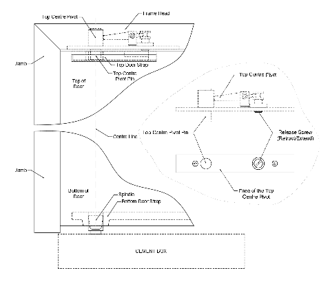
Double Action Door Sets – Floor Spring – Double Action Strap Set (continued).
• To fit the door into the frame, lower the door onto the ‘Spindle’ ensuring correct location into the ‘Bottom Door Strap’. Then rotate the door to 90° and ensure the door is being held secure in position before carrying out the next steps.
• Turn the ‘Release Screw’ anti-clockwise to retract the ‘Top Centre Pivot Pin’ and position the door so that the ‘Top Centre Pivot Pin’ locates into the ‘Top Door Strap’.
• Lower the ‘Top Centre Pivot Pin’ into position in the ‘Top Door Strap’ by turning the ‘Release Screw’ clockwise. Once it’s fully extended into the housing, close the door slowly ensuring the leaf fully closes into it’s frame.
IMPORTANT: Check and ensure the ‘Release Screw’ is fully extended into the ‘Top Door Strap’.
Special Instructions
Double Action Door Sets – Floor Spring – Double Action Strap Set (continued).
Contents – (Part 4)
ANOSCREEN – Timber Screens – Handling & Storage
Handling
Timber screens where possible are palletised for forklift truck off-loading.
In certain instances where a screen is oversize these may be sent as individual items and will require a degree of manual handling.
Timber screens can be heavy and difficult to lift and manoeuvre so you must take care to avoid injury when doing so. A manual handling assessment will be required when handling our timber screen products on site.
Always work in strict accordance with your site manual handling policy.
Storage
Timber screens should always be stored in a dry, enclosed environment – the relative humidity of the storage area and the finalised location should fall within 40-60% relative humidity. The moisture content of our screens is between 12-14% and products stored outside of our guidelines may shrink, swell and distort and will therefore not be guaranteed by Hanson & Beards Ltd.
If glass has been supplied loose it must be stored on either a purpose-built stillage or stored upright with each piece supported to prevent damages.
Glass must be kept in a dry environment and should never be stored outside or exposed the outdoor elements. Water ingress can damage fire rated glass panels.
Special Instructions
ANOSCREEN – Timber Screens – Glazing Bead
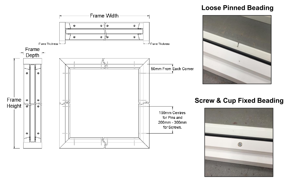
Screens can be supplied with different fixings dependent on their required specifications for fire ratings.
All beads are pre-fitted in our factory. One side of the glazing bead is permanently fixed in place to provide the datum and the opposite side is loose fixed for removal and re-fitting on site.
Pins shall be positioned at 150mm centres.
Where screw fixed bead is required, the screws will be supplied with a cup fitting. The screw positions will vary between 200mm and 300mm centres, depending on specifications for fire ratings.
ANOSCREEN – Timber Screens- Single Screen Fixing
Things To Consider:
Ensure the structural opening is plumb and square before carrying out any installation.
Hanson & Beards timber screens are manufactured to a dimension of 14mm (± 2mm) in height and in width than the specified structural opening dimensions given.
Ensure you have at least 5mm clearance between the perimeter of the structural opening and the screen frame before starting.
Installation Steps:
- Position the screen centrally in the width of the structural opening. Use appropriate packers between the screen frame and prepared opening immediately above each fixing point.
- Ensure the screen frame is both plumb and square and the fixing points are securely packed and cannot be distorted when fixed with screws.
- All fixings need to be in solid material with a minimum of 40mm of anchorage into the wall construction (soft mortar joints are not suitable fixing points).
- Fixings can be positioned behind the glass panel and bead to conceal them. However, you must satisfy yourself that the fixing points are robust enough.
- Heavy/bulky screens may require paired fixings and we recommend that your fixings are 100mm in from each corner and no more than 600mm at centre points.
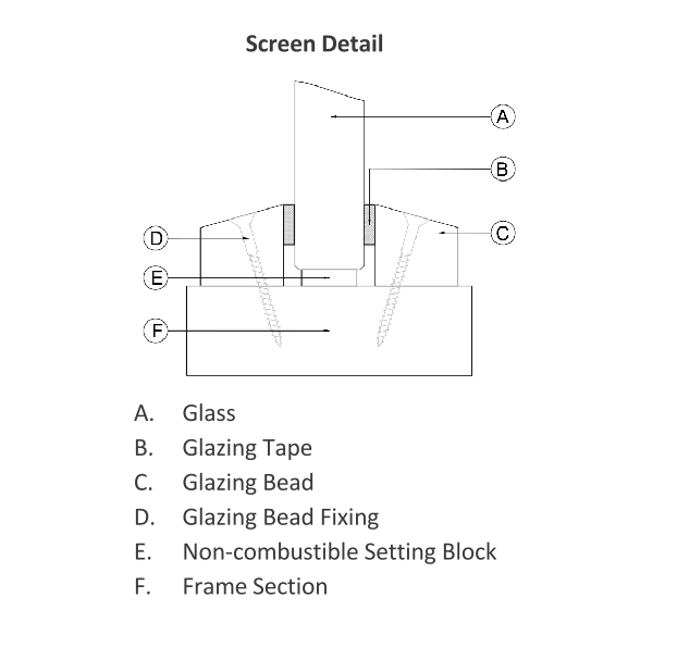
- To avoid glass slippage during and after installation, cement/calcium silicate-based non-combustible setting blocks are to be used to centralise the glazing within the frame. Glass slippage could lead to premature failure of the glazed aperture so you must satisfy yourself that the pane is firmly fixed in place.
- Fire rated screens will require back-filling. Please refer to pages 35 & 36.
Special Instructions
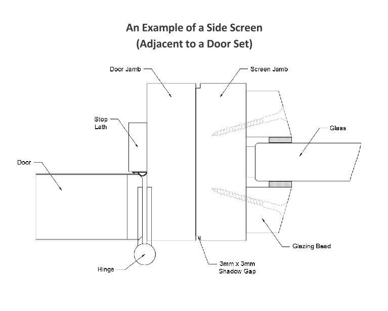
ANOSCREEN – Timber Screens – Side Screen Fixing (Adjacent to Door Frames).
When using separate frame sections (as shown to the right) each section must be suitably fixed to one another using appropriate steel screws and glued using Urea Formaldehyde or Polyurethane. Screws must be fixed at 600mm centres and locate to approximately 2/3 of the depth of the adjacent timber section. It is permitted to have a 3mm x 3mm shadow gap at the frame joint, however, the joints must be tight with no gaps.